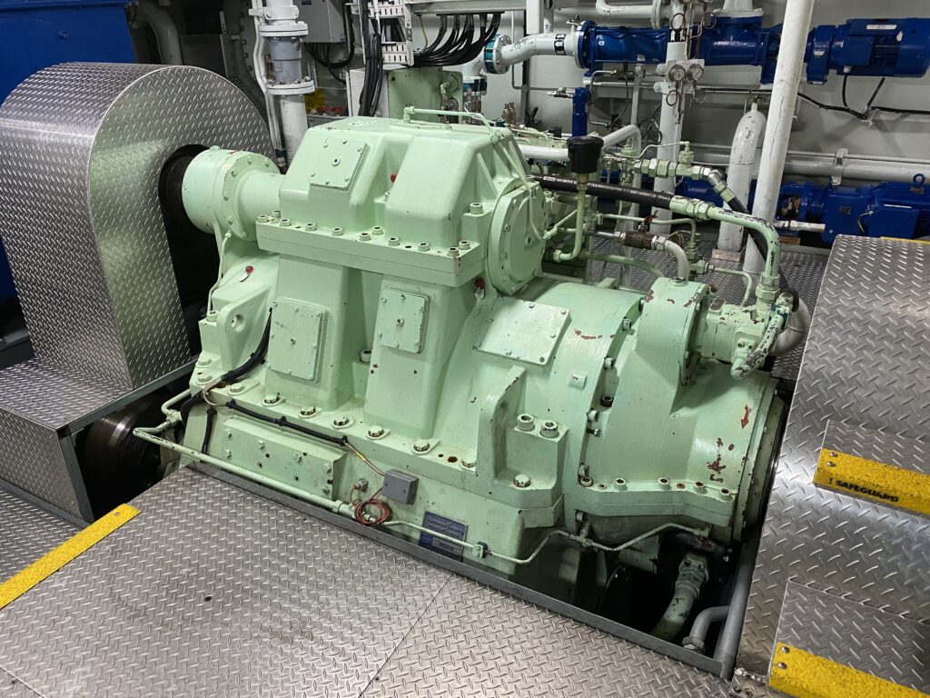
The marine gearbox is almost similar to what we can find in automobiles. As the name suggests, it is housed in an enclosed metal box.
Marine gearboxes are commonly mounted securely at the engine’s driving end and are in-between the engine shaft and propeller shafts. Engines are usually connected to gearboxes via mounting plates or flanges, the same way gearboxes are connected to propeller shafts. These types of machinery consist of gears, hub, clutch, pressure plates, input coupling, output coupling and etc.
What is the function of the marine gearbox?
These transmissions mainly provide a clutching arrangement for boats: clutch in or clutch out.
Clutch in, to engage the load shaft (e.g., propeller shaft) to the gearbox, and so to the driving engine that is always fixed, connected to the transmission. Clutching in can either be forward clutch (ahead) or reverse clutch (astern).
In propulsion, especially on small boats, this gearbox function gives the propulsion direction. As for safety, the engines cannot be turned on/started unless the gearbox is in the neutral clutch or in simple terms clutched out.
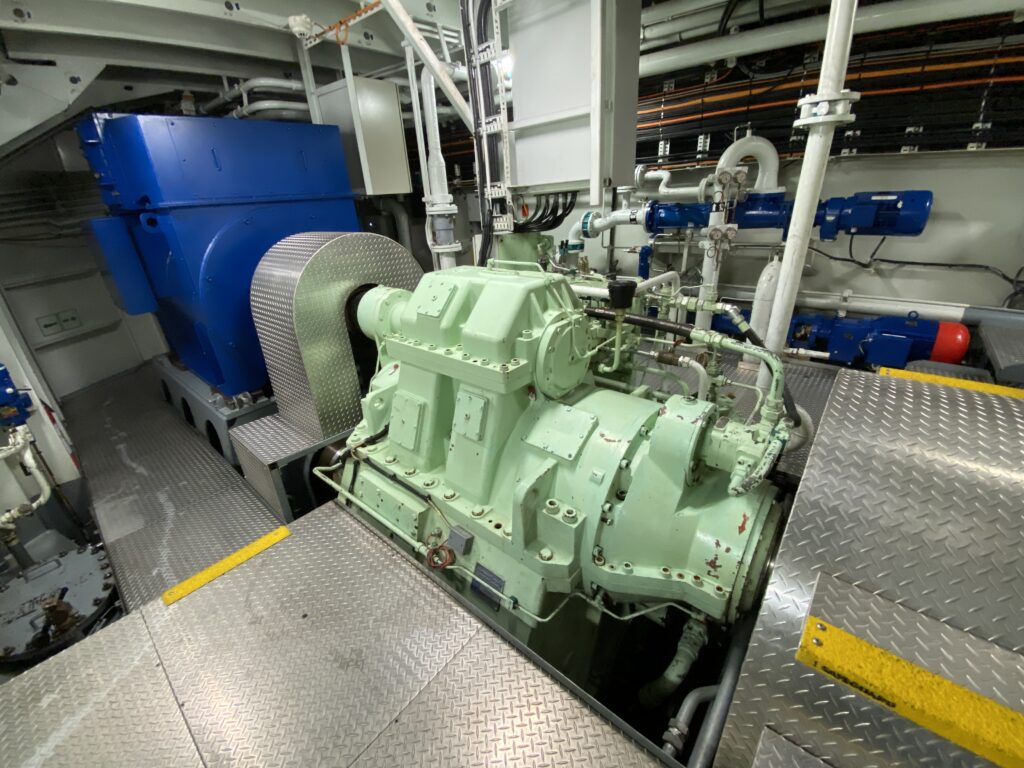
In addition, gearboxes are used to reduce or deduct the rpm of the driving end to the consumer or load end. The gearbox rpm reduction is used whenever a shaft speed to torque requirement is need to be satisfied.
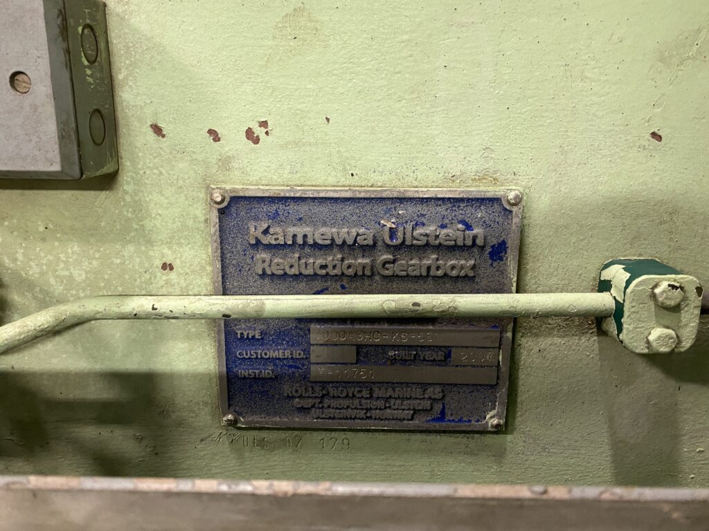
The gearbox ratio is commonly found on the gearbox data plate fastened to the gearbox itself. Basically, this ratio is computed by dividing the driving gear tooth count by the driving gear tooth count.
For example, a 60- toothed gear being driven by a 20-toothed gear has a ratio of 3:1 which means for every three rotations of the driving shaft one full rotation of the driving shaft is produced. Take note that the gear ratio is fixed for every gearbox output.
How does a marine gearbox work?
The gearbox working principle is not as complex as it may sound. For instance, the gearbox is a composite of an internal pump, clutches and gears. The pump purposely exerts pressure on the clutches providing which gears are desired to engage thus creating the movement desired.
Depending on the gear or set of gears engaged the rotation can be clockwise or counterclockwise. No gear engagement also refers to a neutral clutch. The clutch movement is usually transmitted from the Engine RCS or remote-control system to a solenoid valve which orders directly the oil direction to move the gearbox clutch.
The oil pump is internally arranged and is driven mechanically by the driving shaft of the engine.
In addition to its operating principle, most small to medium size boats has twin propulsion set-up and require opposite rotation of the propellers to function and complement boat thrust, ahead or astern without affecting the boat heading or direction.
As mentioned above, a solenoid valve is configured to offer rotation independence-meaning the two engines are synchronously operated as per speed and rotation direction while having an opposite propeller shaft rotation/ direction.
To put it simply the solenoid valve has two positions; Position A- to clutch forward, and Position B to clutch astern.
To order ahead propulsion, the port engine utilizes Position A for Clockwise movement while the Starboard engine utilizes Position B to make a Counter-clockwise movement, thus, creating an opposite shaft movement even the engines are moving in the same rotation direction.
What are the different types of gearboxes?
Gearboxes are distinguished according to their appearance and coupling arrangement thus providing us with three main groups or types: Concentric Gearboxes, Parallel gearboxes, and Right-angle gearboxes.
Concentric Gearboxes
Concentric gearboxes commonly known as in-line gearboxes are usually used for high-torque applications.
These kinds of gearboxes are normally used when a single output is connected to a gearbox. Like in small fast crafts, where two engines are driving two independent propeller shafts independent of each other the gearbox is used for the clutch in (CW or CCW) and clutching out given at a specific gearbox ratio.
The driving and the driven shaft are mounted horizontal, in line with each other for each gearbox. The gearboxes are mounted adjacent to each other representing a port and starboard engine propulsion arrangement.
Parallel gearboxes
Parallel gearboxes are used whenever there are two outputs connected to one input (connected simultaneously) or vice versa whenever are two inputs connected to a single output (connected one at a time).
These gearboxes are for two shafts having high and low-speed requirements. Also like in concentric gearboxes the driving shaft and driven shafts are mounted horizontally where the output shafts are parallel with each other.
As an elaboration to the former described, ships having shaft generators have two output shafts.
The driving engine is connected to the gearbox while it transmits the force driven to a propeller shaft and generator shaft. Commonly ships installed with shaft generators have a fixed or constant engine speed / RPM although to increase ship speed there are using CPP or controlled pitch propeller system.
CPP enables the ship’s propeller pitch to change, invariable to ahead speed and astern speed boat functions. The latter can be seen on ships having diesel-electric propulsion systems where the propeller shaft can be operated under the diesel engines or via electric motors.
On diesel propulsion, the diesel engine is engaged to the gearbox while on electric propulsion the electric driving motor powered by the ship’s generators is engaged to the gearbox.
Right-angle gearboxes
Right angle gearbox is used whenever there is a need to transmit the power produced by the engine driving end to the propeller shaft in a 90 degrees orientation.
In ships, a common application of such is the azimuth thrusters where there is no rudder installed rather the propeller acts as the rudder and propulsion at the same time. The engine is still the driving force for the propeller while it faces the direction desired to steer the ship.
Further applications are the ship’s bow thrusters although they are not propelled by engines instead, they are driven by powerful electric motors.
What causes a boat transmission to slip?
Boat transmission can slip due to different factors commonly they can be due to worn clutches which can get damaged over time considering boat age or can be worn due to external forces. External forces that hinder shaft rotation while the vessel propulsion is active; such as vessel grounding or rope entanglement to propellers.
Furthermore, dirty system oil can also clog the filters disabling the internal pump to create the required pressure to push the clutches and engage the gears desired. Both cause the clutches to slip and disengage which in effect no acceleration is produced.
Why do boats not use transmissions?
With all the functions the gearboxes have to offer discussed above, still, not all ships are using gearboxes/transmissions. Especially if there is no speed variation or torque requirements needed to be satisfied between the engine and propeller shaft application.
On the other hand, ships that do have gearboxes still do not use transmissions like cars have because, in a broad sense, it is too complicated to maintain a bigger transmission for ships that can only offer a narrow speed efficiency.
The propeller as it is turned faster causes the water friction to increase as well making it harder to turn. In addition, the propeller as it is rotated faster in water shortens its lifespan due to cavitation. Costly yet inefficient speed adjustable transmissions are not for ships.
- Types of Gas Carriers as per IGC Code – April 22, 2025
- Wind-Assisted Propulsion Systems (WAPS): A Game Changer for Maritime Decarbonization – February 6, 2025
- 10 Boat Salvage Yards in California – January 25, 2025

