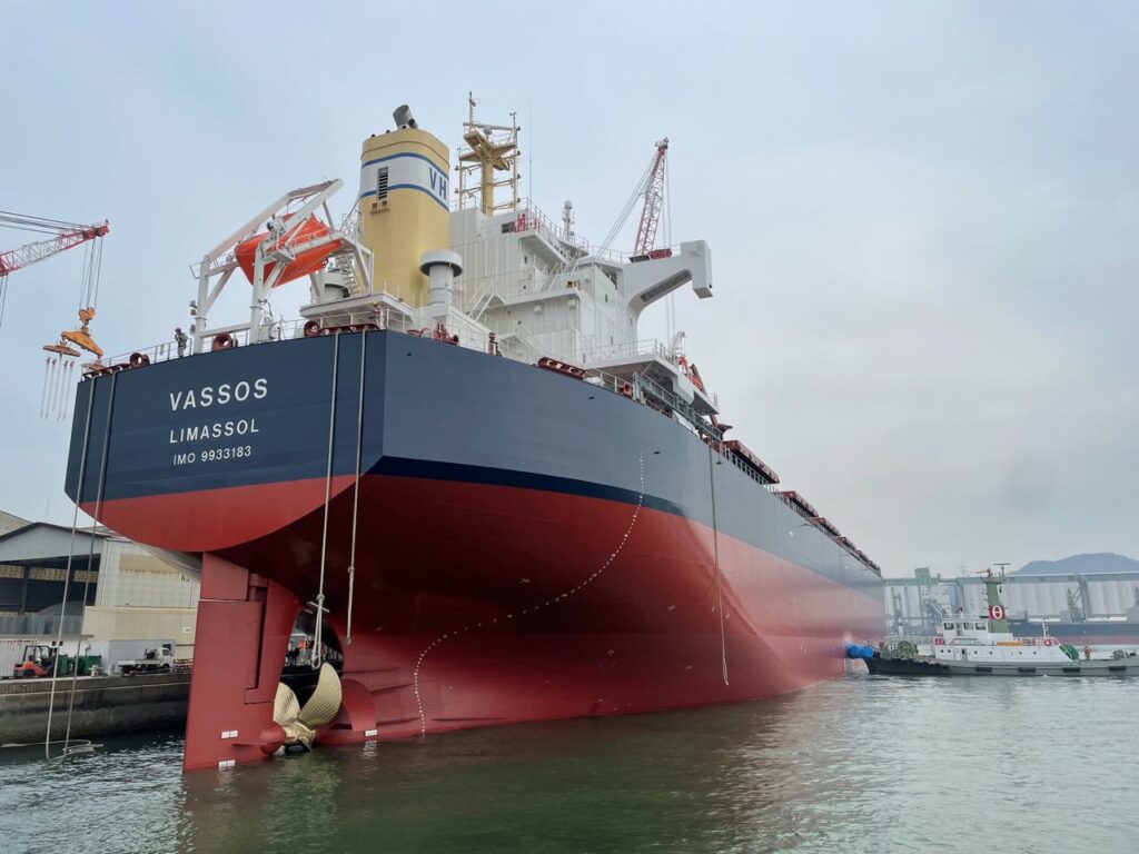
Shell plating can be defined as the exterior surface of a hull that is in contact with the external environment such that it is designed to resist external forces acting on them.
Shell plating is primarily divided into two namely bottom and side plating. The bottom and side plating constitutes the hull of the vessel and are designed such that their primary function is resisting the external forces acting on the hull and making the vessel water-tight.
Deck plating on ships can be defined as those plating that is arranged in the horizontal direction and welded together such that they serve the function of providing deck floorings. They are designed to transfer the bending loads effectively to the entire structure.

What Are The Bottom And Side Shell Plating?
The bottom and side shell plating on ships are combinations of a series of flat and curved plates welded to each other. The vertical welds are referred to as butts and horizontal welds are called seams.
Once the shell plating is developed further stiffeners are attached both longitudinally and transversely to support the plates from transferring the loads efficiently to the entire structure.
- Bottom shell Plating
Bottom shell platings are commonly found to be thicker than side shell plating as they are subjected to more forces as the majority of the hull sections are below the waterline where the hydrodynamics forces are higher when compared to sections that are above the waterline. The bottom shell located at the aft and forward are also subjected to slamming loads which results in higher pressure build-ups.
The thickest section of the bottom plating is the keel plate which runs along the centerline of the hull bottom longitudinally along the length of the vessel. The keel thickness and dimensions remain the same throughout this length. This is done so as to provide extra strength during undesired events like grounding which can fracture the ship’s hull. The adjacent bottom plating normally has a thickness lower than the keel plating.
Starting off from the keel the thickness is designed towards the bilges so as to resist the bending stresses acting on the bottom. Bottom plating further tapers to lower thickness values at the end of the bottom plating. It should be noted that thicker plates are designed for regions that are subjected to slamming forces.
- Side shell plating
Side shell platings are normally found to have lower thicknesses with respect to the bottom shell plating. The maximum values of thickness can be found at 40% forward and aft of the vessel’s midship length which then tapers out. It can be found that higher thickness is designed in regions where vertical shear stresses are high, normally near to the transverse bulkheads such that efficient load transfer is maintained.
Thickness can also be found to be increased in shaft brackets, stern frames, and similar areas which are subjected to repeated loading. Shell plating thicknesses are also increased around the boundaries of openings as stress concentrations are higher at areas of discontinuity. All the openings have rounded corners so as to avoid stress concentrations.
Deck Plating And Its Details
Deck plates are designed to efficiently transfer bending and torsional loads. The thickest deck platings can be found in the boundaries of hatch openings and also around the midship region. Those plating that lie, in line with the hatch openings provide very minimum to the longitudinal strength of the deck and have lower values of thickness.
Design considerations are done so as to provide thicker plates about the midship of the vessel as these regions are subjected to maximum bending stresses. The plate thickness further tapers away after 40% from the midship towards both the forward and aft of the vessel.
It should also be noted that the higher plate thickness is designed for areas subjected to higher stress concentrations and where discontinuities are present. Stiffeners are also attached under the deck plating where typical geometrical profiles like flat, angled, or bulb sections are found to stiffen the plates and effectively transfer the loads.
Shell Plating Design Considerations And The Shell Expansion Plan
The thickness of a shell plating is calculated based on the stresses acting on it with respect to its location. There are both numerical and empirical approaches to this solution. The width and span are considered with respect to the pressure acting on that area and are analyzed to come up with values of thickness for which the material doesn’t fail.
It can be noted that the primary regions with the highest stress concentrations are the bottom plating followed by the side plating and then the deck platings.
What Is Shell Plating Strake?
During the shipbuilding process, all the side plating is named and arranged in sequential order with strake numbers or alphabets. They run longitudinally throughout the length of the hull. Sheer strake can be technically defined as the upper section of the side shell plating which is the uppermost strake.
Sheer strake is made with close considerations in terms of design and construction with respect to classification society rules as they oppose lot of stress during the life of a vessel. As they are placed furthest away from the neutral axis they are made with thicker & stronger steel than the other strakes.
Since sheer strake is one of the most highly stressed regions above the waterline, welds and cutouts are usually avoided which can act as stress raisers.
Also, the upper edges are kept rounded and welding of bulwarks on the edge of the strakes is avoided within the midship area of the vessel where the stress concentration is maximum. Rounded gunwales are usually introduced for the connections between the sheer strake and strength decks where plate thickness is usually higher.
As per classification society rules, the radius of the rounded gunwales should be not less than 15 times its thickness, and welding’s usually avoided on the radiused surface.
Grades Of Steel Used For Shell Plating
Shipbuilding steel can be classified into high tensile and medium tensile steel. High tensile steel is used for highly stressed areas on a vessel. They have a lower thickness-to-weight ratio when compared to steel. They are normally represented as AH 36, BH 40, etc. where the number corresponds to minimum yield strength in N/mm2.
Summary
Shell and deck platings on ships make up the boundaries of all the vessels and are designed to withstand all the external forces acting on them throughout their service period. Periodical surveys are done so as to ensure that the shell and deck plates maintain their integrity such that the vessel is able to do her operations safely.
- Types of Gas Carriers as per IGC Code – April 22, 2025
- Wind-Assisted Propulsion Systems (WAPS): A Game Changer for Maritime Decarbonization – February 6, 2025
- 10 Boat Salvage Yards in California – January 25, 2025


