
The wheel-over point (WOP) is the position where the helm must be applied so the ship turns onto its new track without overshooting. The turning radius is the radius of the arc the ship follows during that turn.
This guide is written for navigating officers and deck cadets preparing passage plans. It covers the wheel-over formula, a worked chart example, the rate-of-turn relationship, and how the wheel-over point is set and monitored on ECDIS.
What Is a Wheel-Over Point?
A wheel-over point is the position on the current track where the officer of the watch orders the rudder to start a planned course alteration. It lies before the waypoint, because the ship needs distance to start swinging.
A large ship cannot turn on a point. If the helm goes over only when the ship reaches the waypoint, it ends up well outside the new track. In a narrow channel, that overshoot alone can put the ship aground.
Wheel-over positions are therefore marked for every significant alteration in confined or coastal waters. They form part of the passage plan, together with the planned turn radius and the method used to monitor the turn.
What Is the Wheel-Over Point Formula?
The wheel-over distance before the waypoint equals the turn radius times the tangent of half the course change. Add the distance the ship runs before it starts to turn.
- Wheel-over distance = R × tan(A ÷ 2) + delay distance
- R: planned turn radius in nautical miles
- A: course alteration in degrees, from the old course to the new course
- Delay distance: distance run between applying the helm and the ship starting to swing, taken from the ship’s maneuvering data
R × tan(A ÷ 2) is the distance from the waypoint back to the point where the turning arc meets the old track. It grows quickly with larger alterations, as the table shows.
| Course alteration (A) | tan(A ÷ 2) | Arc starts before waypoint, R = 1.0 nm |
|---|---|---|
| 30° | 0.268 | 0.27 nm |
| 45° | 0.414 | 0.41 nm |
| 60° | 0.577 | 0.58 nm |
| 90° | 1.000 | 1.00 nm |
| 120° | 1.732 | 1.73 nm |
How Do You Calculate a Wheel-Over Point on the Chart?
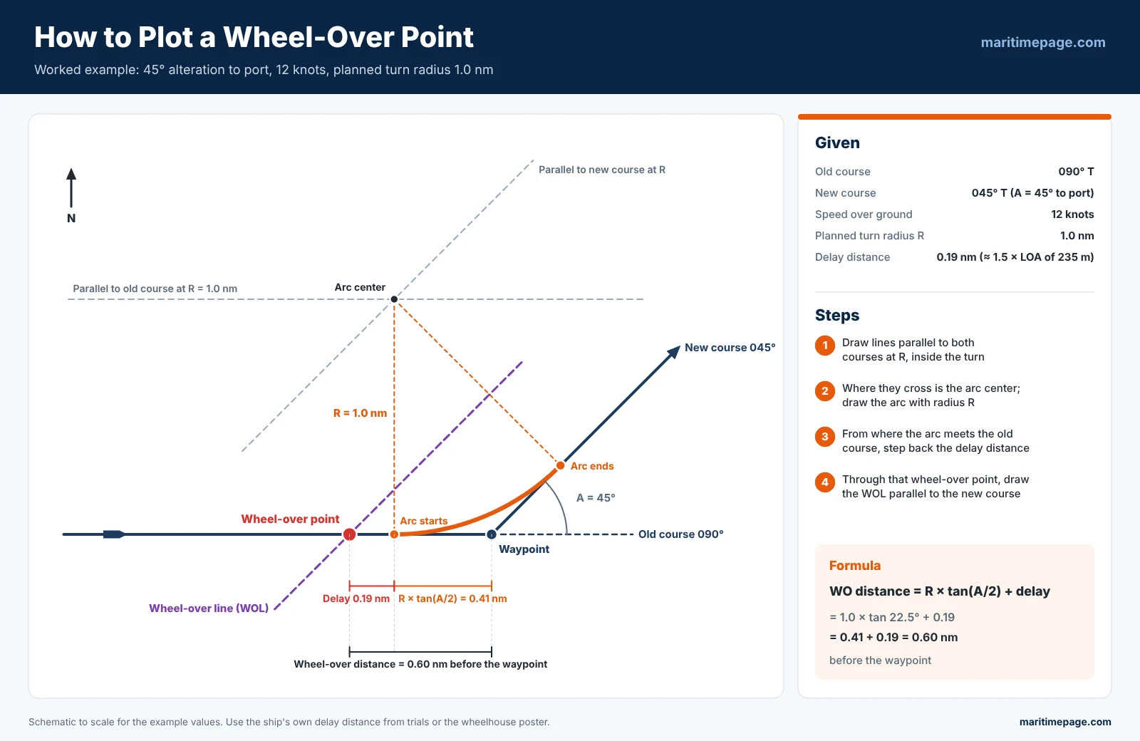
Lay off both tracks, find the arc’s center, and mark where the arc meets the old track. Then step back by the delay distance. The example uses a 45° alteration at 12 knots.
- Current course: 090° T
- Next course: 045° T (an alteration of 45° to port)
- Speed over the ground (SOG): 12 knots
- Planned turn radius: 1.0 nm
- Length overall (LOA): 235 m
- Delay distance: taken here as 1.5 × LOA = 352 m, about 0.19 nm. Use the ship’s own figure from trials or the wheelhouse poster where available.
Step 1: Draw Parallel Lines at the Turn Radius
Lay off both courses on the chart. Inside the turn, draw a line parallel to each track at a distance of 1.0 nm, the turn radius. Where the two parallel lines cross is the center of the turning arc.
Step 2: Draw the Turning Arc
From the center, draw an arc with a radius of 1.0 nm using a pair of compasses. The arc touches the old track and the new track at two tangent points; the first one is where the ship must already be turning.
Step 3: Step Back by the Delay Distance
From the first tangent point, measure 0.19 nm back along the old track. That position is the wheel-over point, where the helm order is given.
Check it by calculation: 1.0 × tan(22.5°) = 0.41 nm, plus 0.19 nm, puts the wheel-over point about 0.60 nm before the waypoint.
Step 4: Draw the Wheel-Over Line
Through the wheel-over point, draw a line parallel to the new course. This is the wheel-over line (WOL).
What Is the Difference Between a Wheel-Over Point and a Wheel-Over Line?
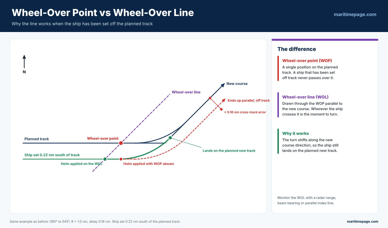
The wheel-over point is a single position on the planned track. The wheel-over line runs through it parallel to the new course, so it still marks the moment to turn when the ship is off track.
If the ship is set 0.1 nm to one side of the planned track, it will never pass over the charted wheel-over point. It will, however, cross the wheel-over line. Applying the helm there brings the ship onto a track parallel to the planned one, which can then be corrected.
What Is the Turning Radius of a Ship?
The turning radius is the radius of the curved track a ship follows while changing course. In passage planning it is a chosen value, and the officer holds the matching rate of turn with moderate rudder.
The planned turn radius is not the same as the ship’s turning circle. The turning circle is the tightest track at full rudder, measured in sea trials. A planned turn uses a larger radius, so there is rudder in reserve to correct for wind, current or a late start.
The IMO Standards for Ship Manoeuvrability, Resolution MSC.137(76), set limits for the full-rudder turning test. The tactical diameter must not exceed 5 ship lengths, and the advance must not exceed 4.5 ship lengths.
What Affects a Ship’s Turning Performance?
- Length and hull form: longer, fuller ships need more room to turn. Turning circles are usually expressed in ship lengths.
- Rudder angle and rudder area: more rudder gives a tighter turn, up to the stall angle.
- Water depth: in shallow water the turning circle can grow markedly, and the ship also suffers squat.
- Draft and trim: a deep draft or a trim by the stern increases the turning circle. Trim by the head reduces it but makes steering erratic.
- List and loading: a list or uneven cargo distribution makes the ship turn differently to port and starboard.
- Engine power and propeller: propeller wash over the rudder increases its effect, especially at low speed.
- Wind and current: both push the ship off its planned arc, especially high-sided ships in ballast.
Speed matters most for timing. At higher speed the delay distance is longer, so the wheel-over point moves further back. A higher rate of turn is also needed for the same radius.
How Is Rate of Turn Related to Turning Radius?
For a constant-radius turn, the rate of turn in degrees per minute is 0.955 × speed in knots ÷ radius in nautical miles. The officer steers to hold that rate.
- ROT (°/min) = 0.955 × V (knots) ÷ R (nm)
- R (nm) = 0.955 × V (knots) ÷ ROT (°/min)
Many officers round the constant to 0.96 or simply 1. In the worked example, 0.955 × 12 ÷ 1.0 gives about 11.5° per minute, so the 45° alteration takes about 4 minutes.
| Speed | R = 0.3 nm | R = 0.5 nm | R = 1.0 nm | R = 1.5 nm | R = 2.0 nm |
|---|---|---|---|---|---|
| 6 kn | 19.1 | 11.5 | 5.7 | 3.8 | 2.9 |
| 8 kn | 25.5 | 15.3 | 7.6 | 5.1 | 3.8 |
| 10 kn | 31.8 | 19.1 | 9.5 | 6.4 | 4.8 |
| 12 kn | 38.2 | 22.9 | 11.5 | 7.6 | 5.7 |
| 15 kn | 47.8 | 28.6 | 14.3 | 9.5 | 7.2 |
| 18 kn | 57.3 | 34.4 | 17.2 | 11.5 | 8.6 |
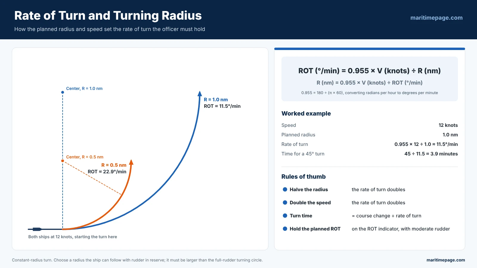
The rate-of-turn indicator on the bridge shows the actual rate. During the turn, the officer adjusts the rudder to keep that reading at the planned figure. Large ships often use modest rudder angles to do this, as their swing builds slowly.
How Is the Wheel-Over Point Monitored on the Bridge?
The wheel-over point is fixed with an independent visual or radar reference, not by ECDIS alone. Common methods are a beam bearing of a charted object, a radar range, or a parallel index line.
- Visual beam bearing: a conspicuous mark coming abeam at the wheel-over point gives a clear “now” moment.
- Radar range: the range to a fixed object ahead or on the bow when the ship reaches the wheel-over point.
- Parallel indexing: an index line on the radar that the target echo reaches at the wheel-over point. It also shows any cross-track error during the turn.
The chosen reference is written on the chart beside each wheel-over point. The OOW, keeping the bridge’s maneuvering data in mind, then knows the radius, rate of turn and speed to hold for every alteration.
What Is an Abort Point?
An abort point is the last position where the ship can still safely stop or turn away before a committed passage, like a narrow entrance. It is marked in the passage plan along with the wheel-over points. Its position allows for the ship’s stopping distance, which for a laden large ship can exceed two nautical miles.
How Are Wheel-Over Points Set in ECDIS?
In the ECDIS route editor, each waypoint carries a planned turn radius and speed. ECDIS then draws the turning arc and can display the wheel-over line or point for each alteration.

Most systems also use an arrival radius, or arrival circle, around each waypoint. When the ship enters it, ECDIS raises an alarm or switches the track-control autopilot to the next leg.
The turn radius entered must be one the ship can actually achieve at the planned speed. Too small a radius gives an arc the ship cannot follow, so track-control will overshoot and cross-track alarms will follow.

Correct wheel-over points keep cross-track error close to zero through each alteration. That matters most in traffic separation schemes, buoyed channels and close to dangers, where sea room is limited.
A late wheel-over carries the ship outside the new track, and an early one cuts the corner. Both reduce the margin to shoal water or other traffic. With the radius, rate of turn and monitoring reference planned ahead, the turn becomes a checked routine, not a judgment call under pressure.
What Do PSC and Vetting Inspectors Check in the Passage Plan?
Inspectors check that a berth-to-berth passage plan exists, is approved by the master and shows wheel-over points for every significant course alteration. They also compare the plan with the ship’s manoeuvring data and the ECDIS route.
SOLAS Chapter V, Regulation 34 requires a voyage plan before sailing, following IMO Resolution A.893(21). The passage plan is a standard item in port state control inspections and a frequently recorded deficiency.
Tanker vetting inspections under OCIMF SIRE 2.0 look at it in more detail, and officers are asked to explain it. RightShip inspections on bulk carriers cover the same ground.
- Wheel-over points or lines marked at each significant alteration, including in pilotage waters.
- Turn radius in ECDIS matching the ship’s turning data, not a default value.
- Parallel indexes, abort points and contingency anchorages where the route is restricted.
- Under-keel clearance and squat checked for shallow sections.
- Plan signed by the master and all navigating officers, and updated when the route changes.
- Track actually sailed, from ECDIS playback or the log, agreeing with the plan.
Common Deficiencies
- Plan covers pilot station to pilot station only, not berth to berth.
- No wheel-over points, or points copied from a template for a different ship.
- ECDIS route with default turn radius and safety settings never adjusted.
- Officers unable to explain how the wheel-over points were worked out.
Frequently Asked Questions
What is a wheel-over point?
It is the position on the current track where the helm is applied to start a planned course alteration. It lies before the waypoint, so the ship comes onto the new track without overshooting.
What is the formula for the wheel-over point?
Wheel-over distance before the waypoint = R × tan(A ÷ 2) + delay distance. R is the turn radius, A is the course alteration and the delay distance is how far the ship runs before it starts to swing.
What is a wheel-over line?
It is a line drawn through the wheel-over point parallel to the new course. It gives the right moment to apply the helm even when the ship is slightly off the planned track.
How do you calculate rate of turn for a ship?
For a constant-radius turn, ROT in degrees per minute = 0.955 × speed in knots ÷ radius in nautical miles. At 12 knots and a 1.0 nm radius, ROT is about 11.5° per minute.
How do you calculate turning radius from rate of turn?
Turning radius in nautical miles = 0.955 × speed in knots ÷ rate of turn in degrees per minute. A ship at 10 knots turning at 10° per minute follows a radius of about 0.96 nm.
What turn radius should be set in ECDIS?
Set a radius the ship can follow at the planned speed with moderate rudder, larger than its full-rudder turning circle. Check the matching rate of turn is achievable, and allow more room in shallow water.
Is the turning radius the same as the turning circle?
No. The turning circle is the tightest track at full rudder, measured in trials. The planned turning radius is a larger value chosen for each alteration, leaving rudder in reserve.
What is the arrival radius in ECDIS?
It is a circle set around a waypoint. When the ship enters it, ECDIS raises an alarm or the track-control system switches to the next leg of the route.

- Great Lakes Maritime Academy: Programs, Cost and Admission – October 14, 2026
- Bunker Delivery Note (BDN): Contents, MARPOL Rules and Checks – October 11, 2026
- Oil Record Book: Part I and Part II Entries, Rules and PSC Checks – October 11, 2026


Leave a Reply